Repairing the arm
If you are unable to use the arm mounted on Care-O-bot 3, you may want to check with the appropriate tools from the manufacturers if the hardware is responding properly. Afterwards, it might become necessary to disassemble the arm and check or replace parts of the hardware.
Using the manufacturer’s software
To read the arm’s status using the manufacturer’s software, you need the following items:
Windows (10) Computer/Laptop with internet connection (for downloads)
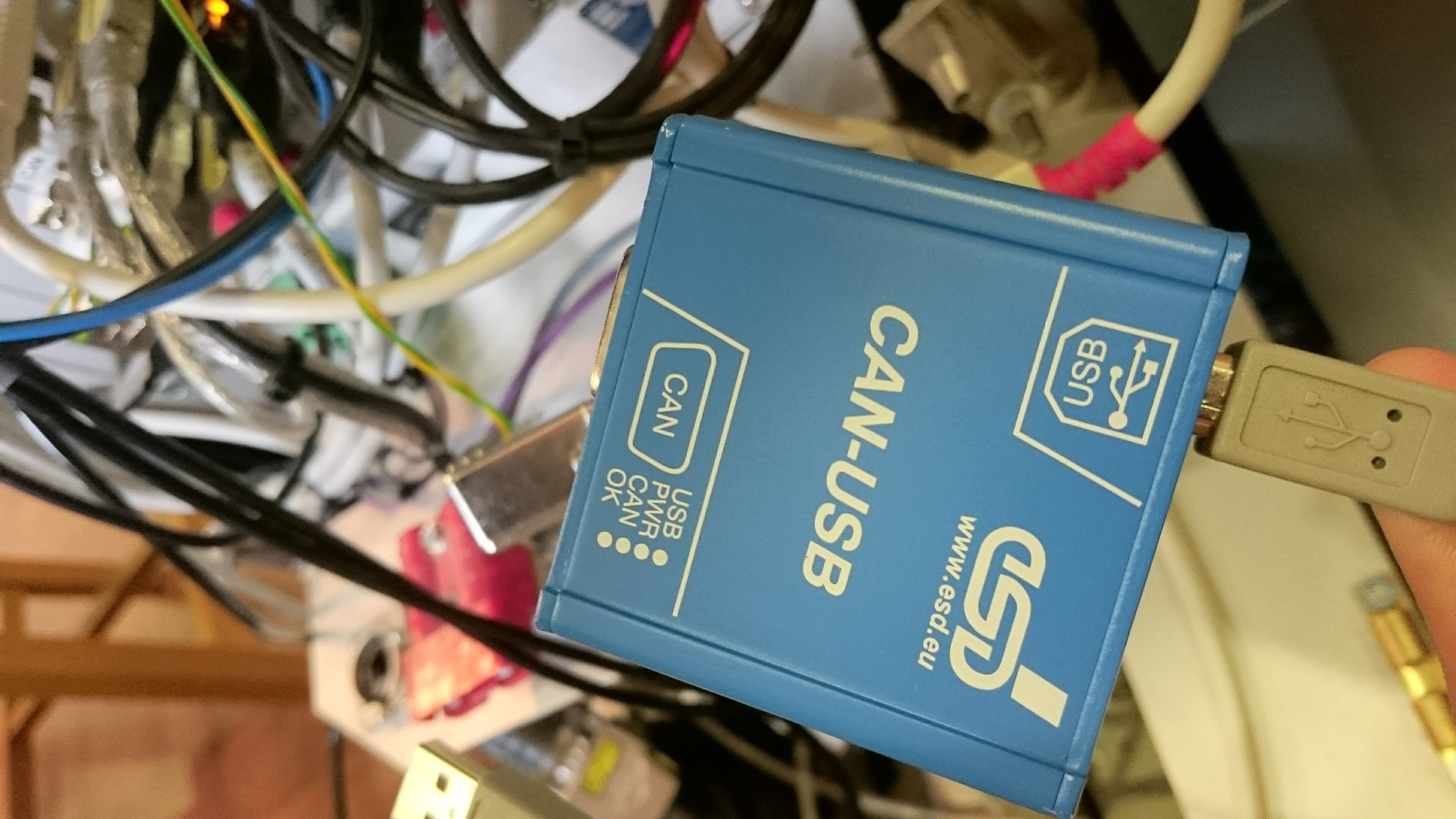
An esd CAN-USB/2 device (confirmed working but CAN-USB Mini might also work):
Matching USB cable (probably type A <-> type B)
Download and install the following software:
CAN-USB/2 drivers from esd (free account required)
PowerCube software from Schunk
To investigate the error, follow these steps:
Connect the CAN-USB/2 device to your computer
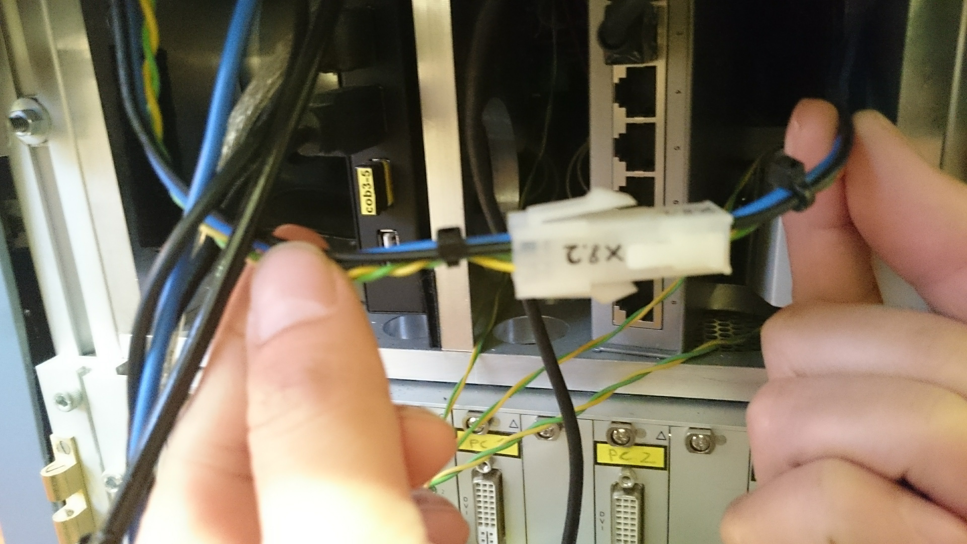
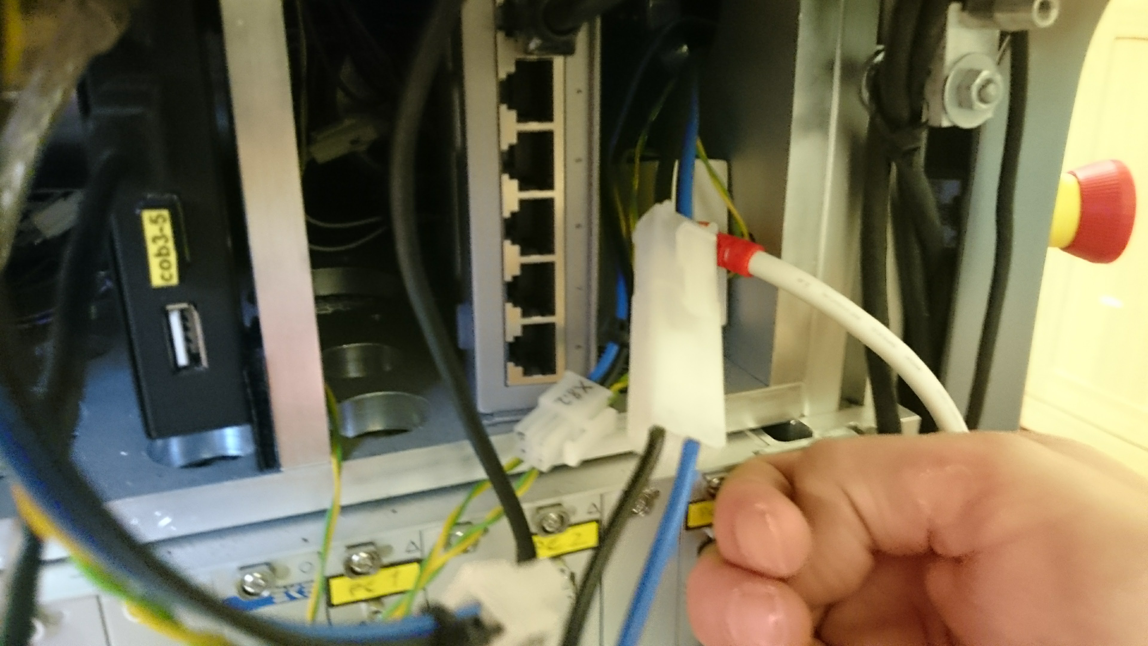
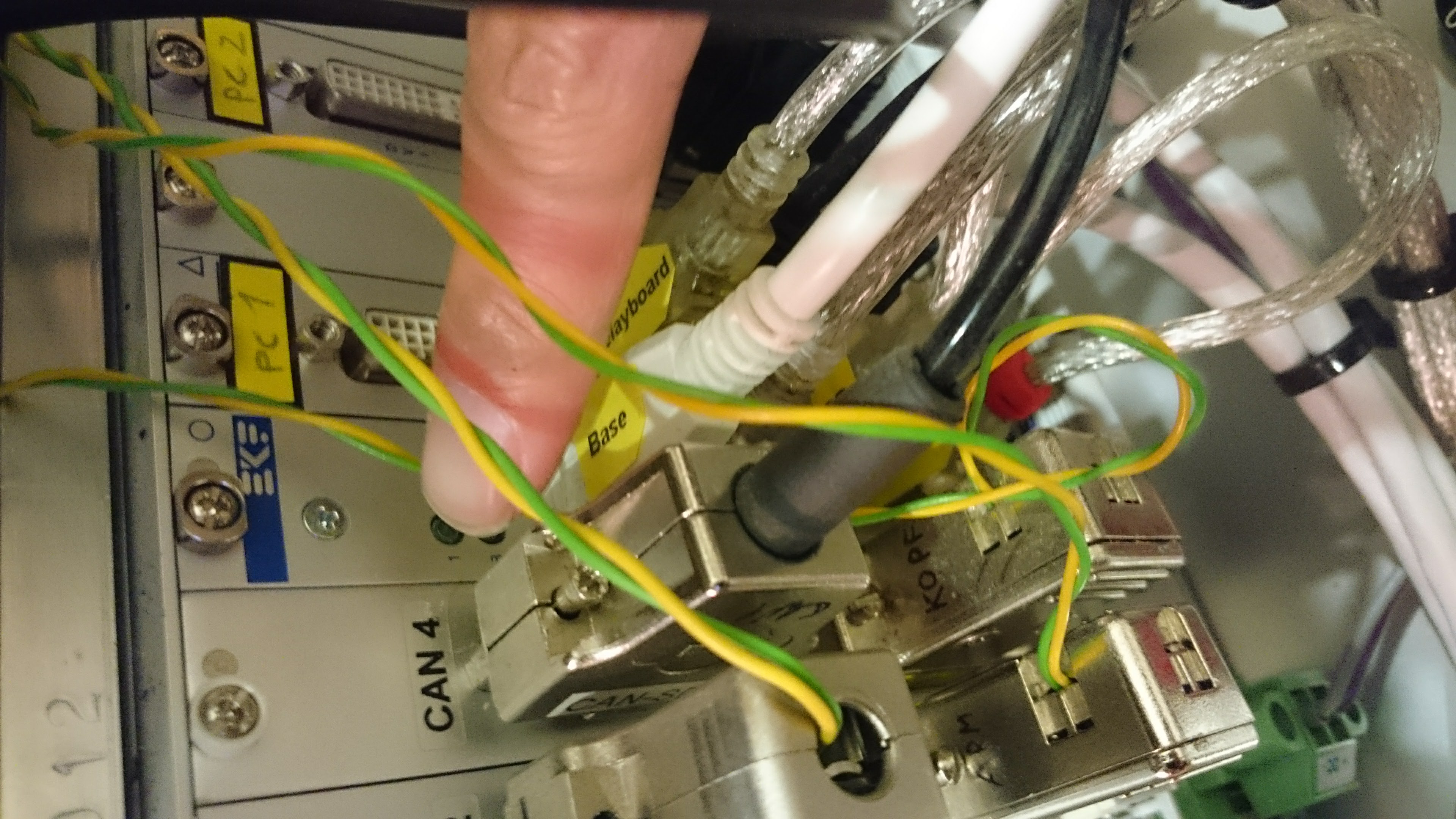
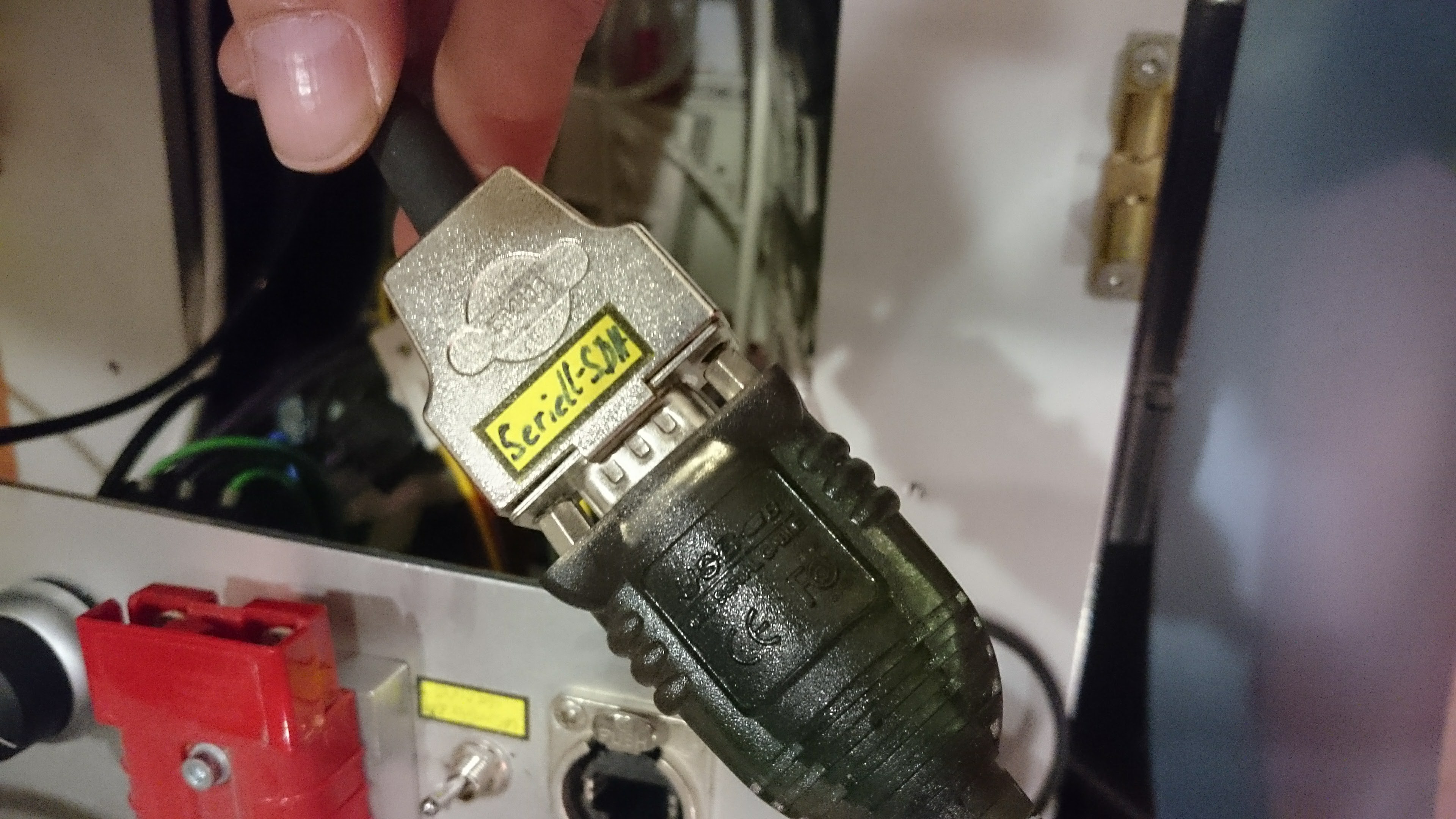
Disconnect the arm’s serial cable from the robot at
CAN 4Connect the cable to the CAN-USB/2 device
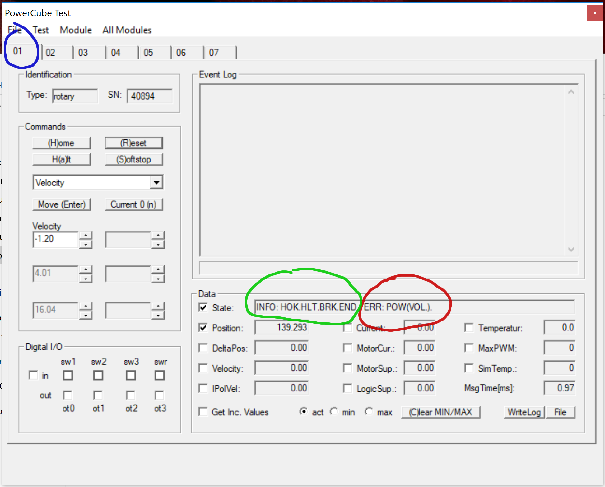
Check joint states with PowerCube:
You can tell whether the joint is on-line and has power by looking at the state field.
In the above example, joint number 01 does not have power (red) but the controller is working fine (green).
The other joints can be accessed by selecting the appropriate tab in the top of the application (blue).
Arm disassembly
To disassemble the arm, you need the following devices:
Allen key set
Electronic screwdriver set
Camera or mobile phone
Warning
Before you modify anything, be sure to take pictures of how things looked when still assembled.
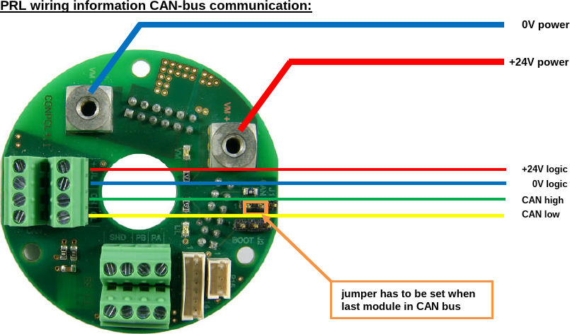
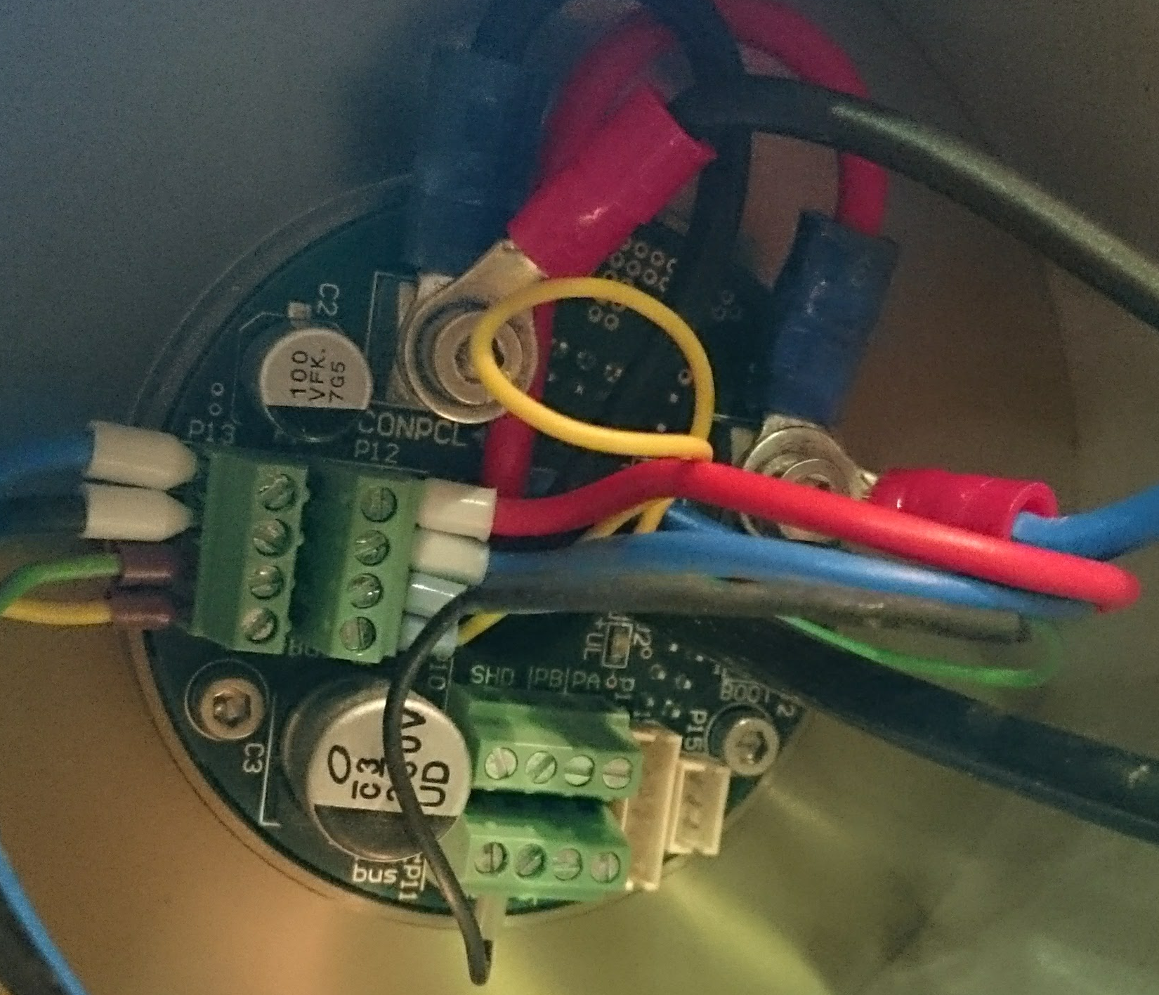
In case you mixed up something, you can find reference pictures of the arm wiring and a connection board here as well.
Remove the arm from the robot
Warning
Do not disassemble the arm alone, work in a pair of two people!
Follow these steps:
Take photos of the wiring between the arm and the robot
Disconnect all wires between the arm and the robot
One person loosens the arm’s screws with an allen key while the other person fixates the arm
Place the arm on a firm surface
Wiring of the arm at the robot:
Remove the connection board
Follow these steps:
Take photos of the wiring
Disconnect the wires on the front side using the screwdriver
Carefully pull the connection board towards you, some pins are still plugged into the board from behind
Wiring of the front side of the connection board:
Replace a broken fuse
If you suspect a broken fuse like in the above example, you have to disassemble the arm first. Additionally, you need the following devices:
A multimeter
Two soldering irons with small tips
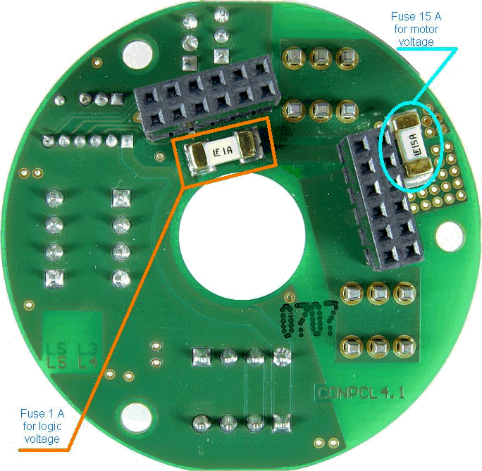
In the arm of Care-O-bot 3, there are two fuses located at the flip side of each connection board. You can check if they are working with the multimeter.
When replacing the fuse, make sure you replace the correct one.
One 15A fuse is for the motor, while the 1A fuse belongs to the controller.
Both should be soldered on two pads at the same time (use preferred a customized soldering tip or two small soldering tips).
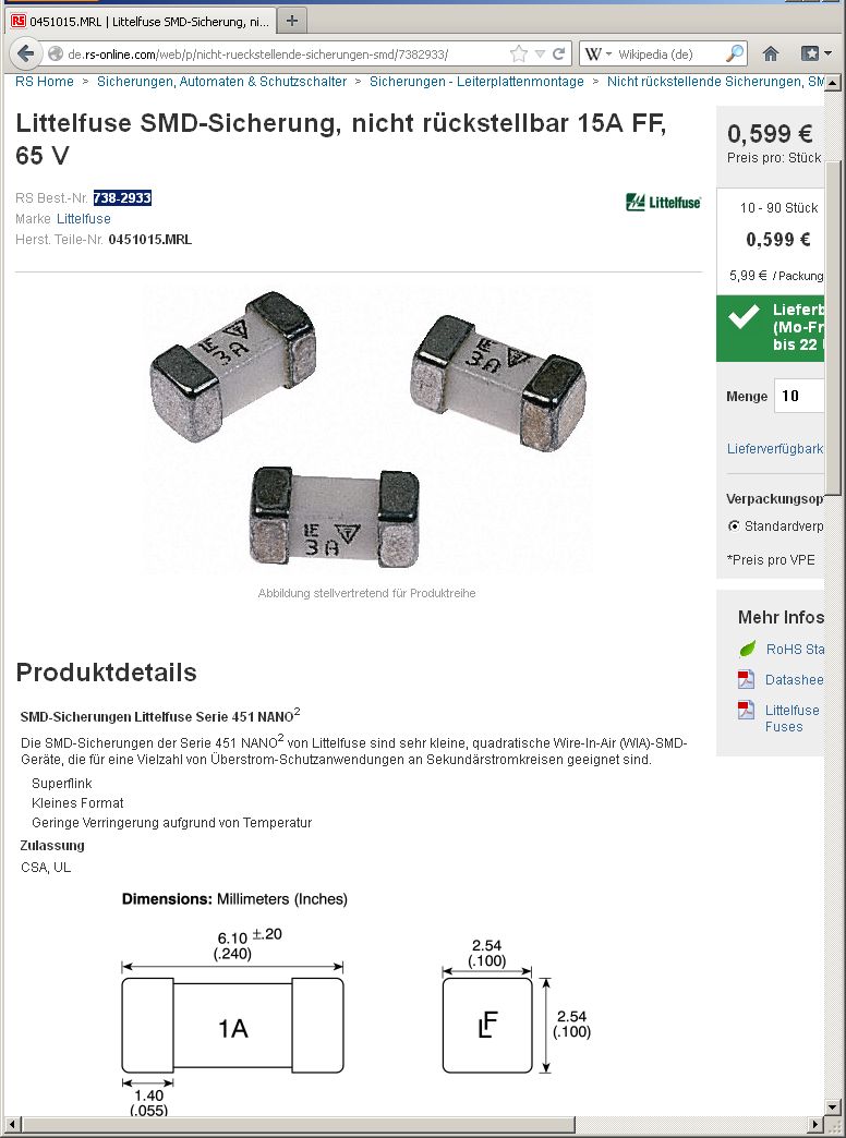
See below snapshot from the supplier’s store depicting the 15A fuse model that is used in the robot.
